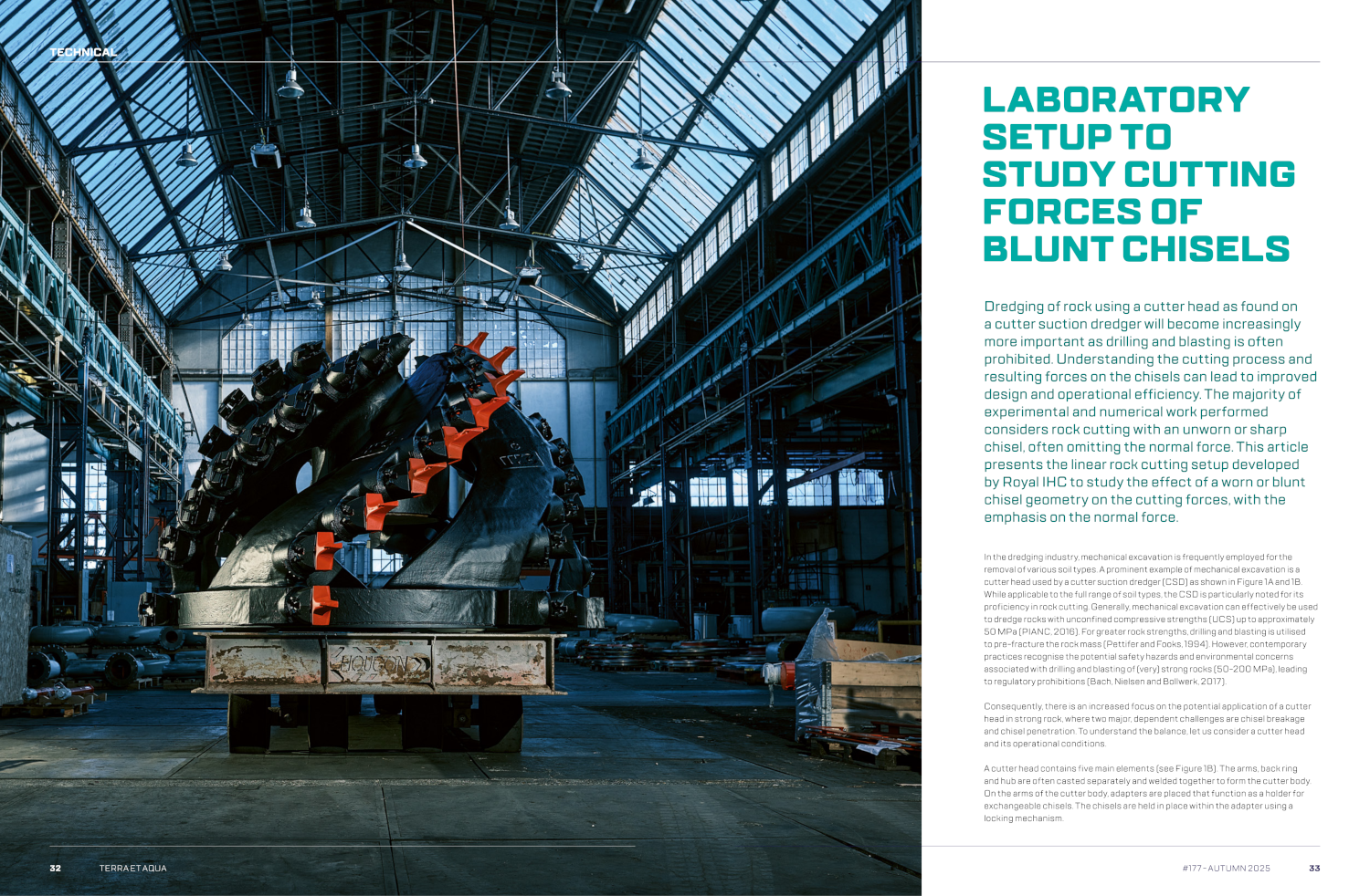
Dredging of rock using a cutter head as found on a cutter suction dredger will become increasingly more important as drilling and blasting is often prohibited. Understanding the cutting process and resulting forces on the chisels can lead to improved design and operational efficiency. The majority of experimental and numerical work performed considers rock cutting with an unworn or sharp chisel, often omitting the normal force. This article presents the linear rock cutting setup developed by Royal IHC to study the effect of a worn or blunt chisel geometry on the cutting forces, with the emphasis on the normal force.

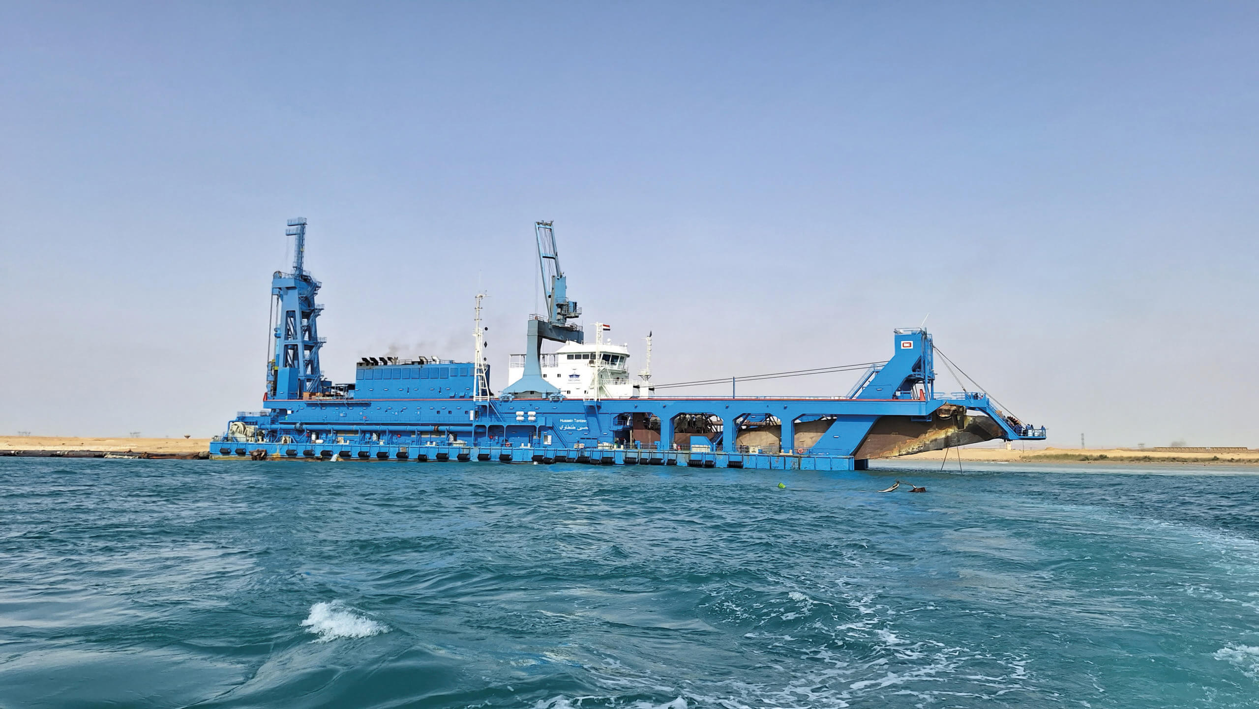
In the dredging industry, mechanical excavation is frequently employed for the removal of various soil types. A prominent example of mechanical excavation is a cutter head used by a cutter suction dredger (CSD) as shown in Figure 1A and 1B. While applicable to the full range of soil types, the CSD is particularly noted for its proficiency in rock cutting. Generally, mechanical excavation can effectively be used to dredge rocks with unconfined compressive strengths (UCS) up to approximately 50 MPa (PIANC, 2016). For greater rock strengths, drilling and blasting is utilised to pre-fracture the rock mass (Pettifer and Fooks, 1994). However, contemporary practices recognise the potential safety hazards and environmental concerns associated with drilling and blasting of (very) strong rocks (50-200 MPa), leading to regulatory prohibitions (Bach, Nielsen and Bollwerk, 2017).

Consequently, there is an increased focus on the potential application of a cutter head in strong rock, where two major, dependent challenges are chisel breakage and chisel penetration. To understand the balance, let us consider a cutter head and its operational conditions.

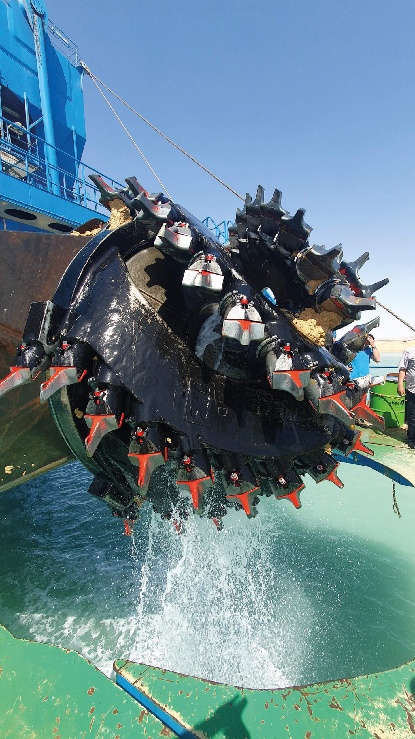
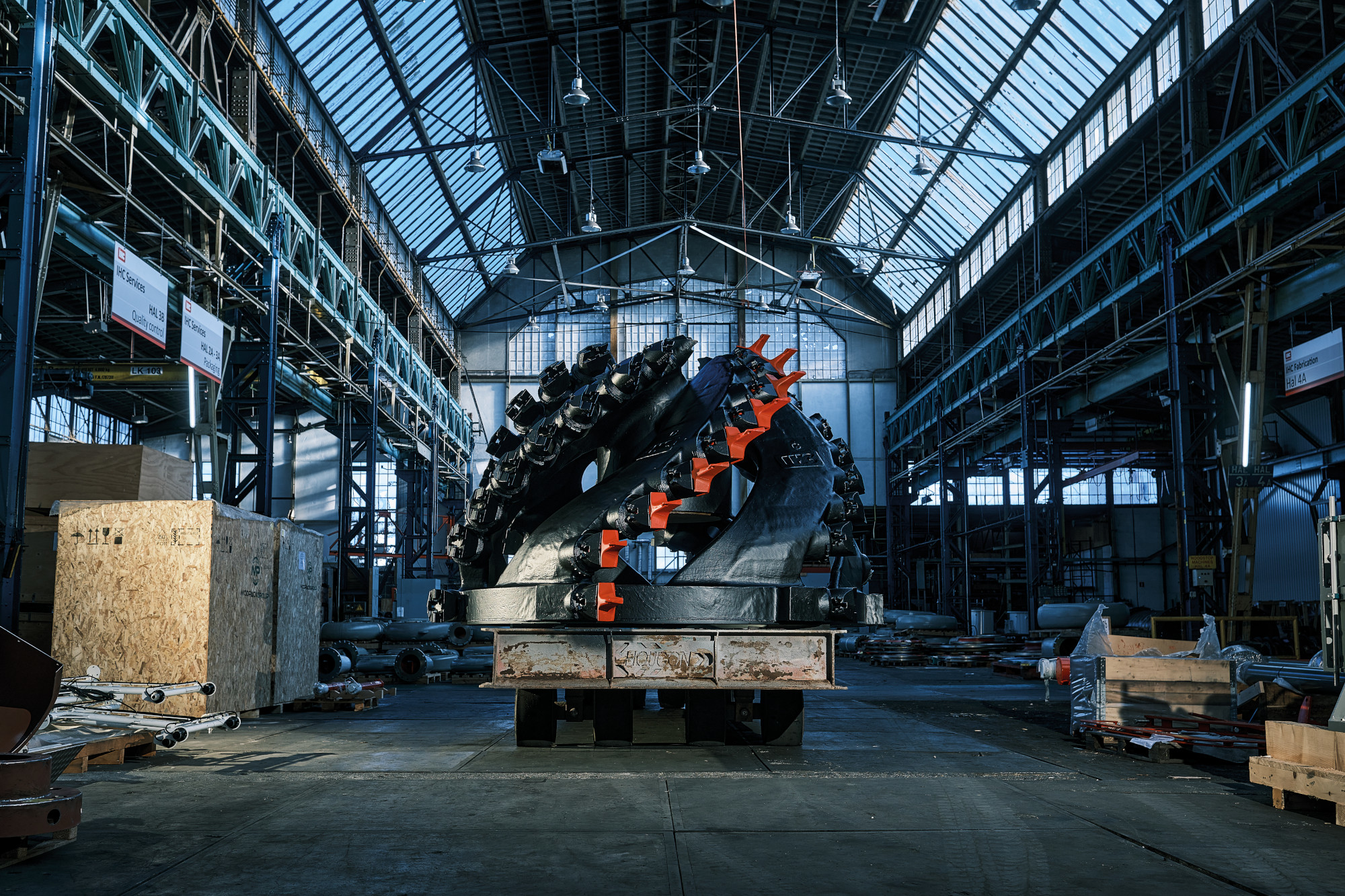
A cutter head contains five main elements (see Figure 1B). The arms, back ring and hub are often casted separately and welded together to form the cutter body. On the arms of the cutter body, adapters are placed that function as a holder for exchangeable chisels. The chisels are held in place within the adapter using a locking mechanism.

FIGURE 1A

Royal IHC build CSD Hussein Tantawy

FIGURE 1B

Royal IHC cutter head

To withstand the cutting forces in rock, chisels have a tapered design. As the chisels are subjected to abrasive wear (Verhoef, 1997), their length decreases over time. This length is known as the wear length and is defined between the tip of a new chisel and the wear mark indicator. Due to this tapered shape, the cross-sectional area of the chisel tip increases as a function of the wear length, generating a wear flat area. The existence of the wear flat area reduces the stresses at the chisel tip by changing the tip profile from an edge to a plane. This is known in the industry as a “blunt” chisel and results in an increased resistance to penetrate the rock mass. The wear flat area in combination with the operational conditions of the dredger determine the penetration behaviour.

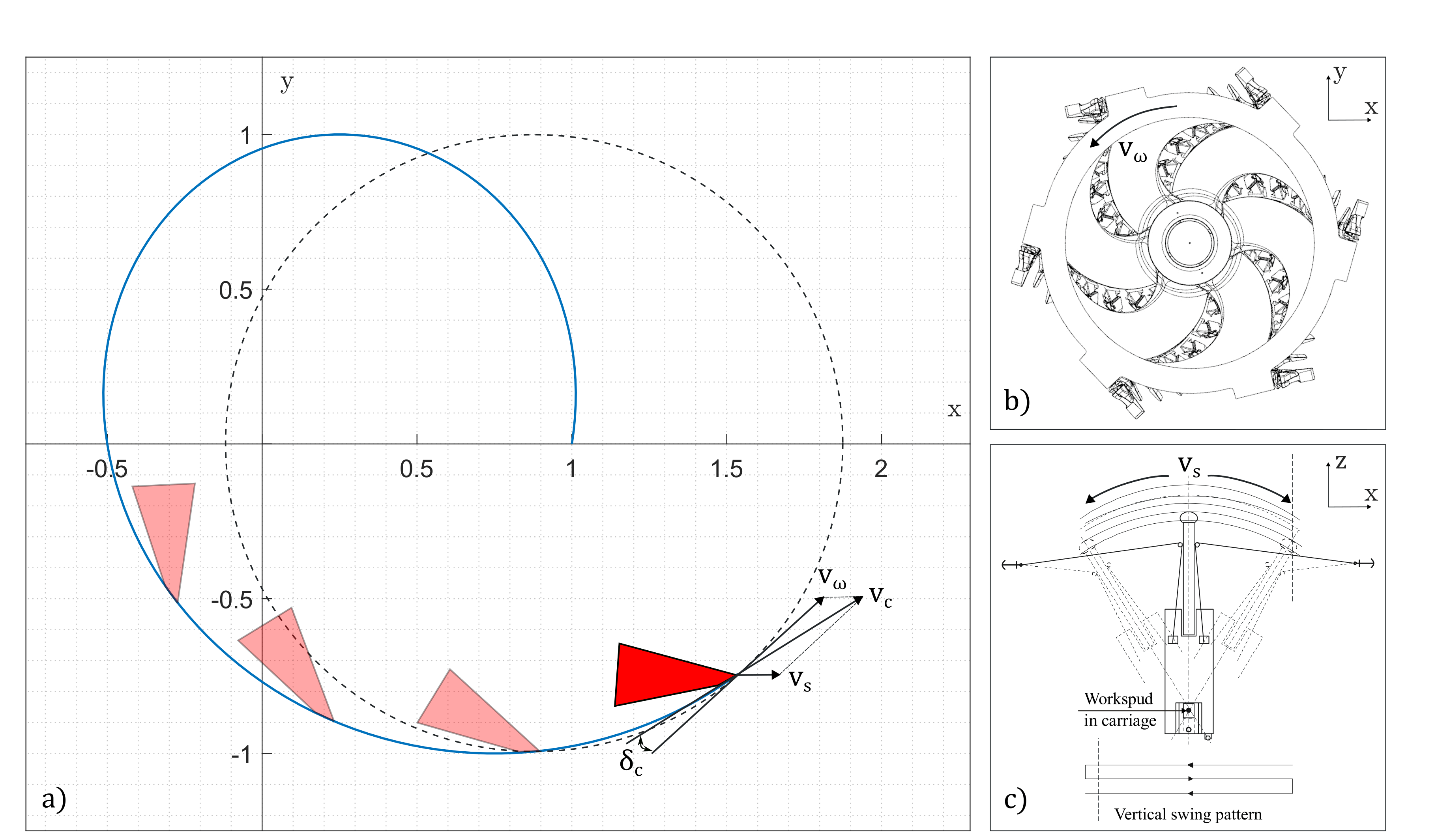
During rock excavation, the cutter head is typically rotating at 15 to 30 RPM, resulting in a circular chisel trajectory and an angular velocity (Vw)(Figure 2A and 2B). As cutter heads have increased to approximately 4 metres in diameter, tangential velocities have raised increased up to 7 metres per second (m/s). Next to the rotational velocity, a horizontal swing velocity (Vs) is present due to the swinging motion of the dredger. The swing velocity is often found to be in between 10 and 20 metres per minute (m/min). The addition of this horizontal velocity component changes the trajectory from circular to helical (see Figure 2A and 2C) and results in the total or cutting velocity. (Vc)

FIGURE 2

Chisel trajectory (A), rear view cutter head (B) and working principle CSD (C).

Due to the difference between the angular velocity (Vw) and the cutting velocity (Vc), an angle δc is found. This angle determines the difference between the chisel static angle (circular trajectory) and the chisel dynamic angle, due to the addition of the swing motion. Although the swing velocity is an order of magnitude smaller than the rotational velocity, the difference between the static and dynamic angles can theoretically be up to 4 degrees. Note that this difference is dependent on the chisel location and corresponding trajectory. The dynamic angle equals zero when the angular velocity (Vw) and the swing velocity (Vs) are aligned, i.e. when the cutting velocity (Vc) is exactly horizontal and has a maximum when both vectors are perpendicular.

The size of the wear flat area combined with the dynamic behaviour of the chisel directly affects the penetration in the rock mass and the cutting forces. Although this principle is known in the industry, little is known about the influence of a wear flat area in combination with the dynamic angles on the magnitude and direction of the cutting forces on the chisels. Some experimental work was performed where a blunted chisel (tip radius) was used to linearly cut dry coal (Daziel and Davies, 1964). It was found that the addition of a tip radius affects the normal force (Fn) to such an extent, that its magnitude can be similar to the cutting force (Fc) (see Figure 4). As the cutting force is also affected by blunting, the ratio average cutting force to average normal force (Fc / Fn) is often used to compare different chisel geometries. For a sharp chisel, a ratio of Fc / Fn ≈ -10 was found. This results from a dominant cutting force and slightly negative normal force when the chisel is sharp, meaning that the chisel will be pulled deeper into the rock. For the blunt chisel a ratio of approximately 1.6 was found for different radii (Evans, 1965).

Detournay and Defourny (1992) published the start of a phenomenological model using a polycrystalline diamond compact (PDC) bit in a drilling application based on a suggestion of Fairhurst and Lacabanne (1957). The phenomenological model that is postulated includes cutting the rock (similar to sharp tools) and frictional contact underneath the tool due to the addition of a wear flat. Experimental observations using PDC bits with a rotational velocity and a rate of penetration suggested that a boundary layer of failed rock is formed underneath the wear flat area (Glowka, 1987). A schematic representation of this process is given by Dagrain and Richard (2006) and Helmons (2017) and is amended to a chisel (shown in Figure 3).

FIGURE 3

Phenomenological model rock cutting using a PDC bit and chisel (after Dagrain and Richard, 2006).

Although the process described is governed by different kinematics and tool geometry, it is expected that this phenomenon will play an important role in understanding the physics while cutting rock with a blunt chisel. This currently is insufficiently understood.

As dredging is most often executed below the water table, saturated rock conditions should be considered. Saturating the rock sample can have physico-chemical effects (Helmons et al., 2016) reducing the mechanical properties such as the tensile strength (TS) (Wong and Jong 2014), UCS (Zhou et al., 2016) and chipping efficiency (Bejari and Hamidi, 2023), and therefore cannot be neglected.

This article describes the experimental setup designed and built at the Royal IHC laboratory to study the effect of a blunt chisel geometry on the cutting forces with the emphasis on the normal force. The setup aims to cover novel subjects, such as saturated rock conditions, relatively large cutting depth with respect to the tool width and a wear flat area in combination with a negative clearance angle and positive rake angle. Three comparable experiments are shown where the accuracy and repeatability of the setup are discussed. Subsequently, two preliminary experiments are shown where the cutting and normal force of a sharp chisel are compared to those using a blunt or worn chisel geometry.

FIGURE 4

Schematic representation of a simplified chisel and unrelieved linear cutting experiment.

TABLE 1

Chisel properties.

Methodology

To study the cutting forces of a blunt chisel cutting rock, the chisel used during the experiments was simplified such that the parameters of interest can be incrementally varied. A schematic representation of a simplified chisel is shown in Figure 4. Here, wt is the width of the chisel,α the rake angle, γ the (back) clearance angle and Lwf the wear flat length. The chisel as shown in Figure 4 is known as an unworn or sharp chisel. Although similar experimental setups have a chisel that follows a circular trajectory (Barker, 1964), it zone was decided to simplify the motion of the chisel to a linear trajectory. This reduces the overall complexity of the experimental setup and allows for a rigid and steady state measurement of the cutting forces.

Considering Figure 4, the cutting force (Fc) is defined as the reaction force on the chisel in opposite direction of the cutting velocity (Vc) . The normal force (Fn) is defined perpendicular to the cutting velocity in the vertical plane and the side force (Fs) perpendicular to the cutting velocity in the horizontal plane. A schematic groove during an experiment (cross-sectional view) is shown where the forward breakout angle f) and the cutting depth are (dc) indicated. The cutting depth is defined as the distance between the free surface of the rock sample and the tip of the chisel. Furthermore, a typical result of an unrelieved linear cutting experiment is shown where the side breakout angle s) is indicated.

FIGURE 5

Linear rock cutting setup at the Royal IHC laboratory: vertical load cell (1); horizontal load cell (2); rock sample (3); and basin including rock sample clamp (4).

Linear rock cutting setup

The linear rock cutting setup (LRCS) was designed and custom-built in the Royal IHC laboratory (see Figure 5). In our setup, it was chosen to drive the chisel by a hydraulic cylinder, simplifying testing on saturated and submerged rock samples. The hydraulic cylinder has a stroke length of 1180 mm and a pulling force capacity of approximately 5 tonnes. The cylinder is attached to a hydraulic power unit (HPU) that is capable of driving the carriage to a steady state cutting velocity in the range of 0.01 to 0.23 m/s (force controlled).

The rock sample is placed in a basin that allows for full submersion and contains a clamping frame to fix the rock sample to the basin (elements 3 and 4 in Figure 5, respectively). The maximum dimensions of the rock sample are 1100 x 300 x 300 mm. To eliminate any relative displacement between the rock

The rock sample is placed in a basin that allows for full submersion and contains a clamping frame to fix the rock sample to the basin (elements 3 and 4 in Figure 5, respectively). The maximum dimensions of the rock sample are 1100 x 300 x 300 mm. To eliminate any sample and the chisel other than the cutting velocity, braces are installed on both sides of the basin in the direction of the cutting velocity.

relative displacement between the rock

Instrumentation

The chisel is placed in the measuring section of the LRCS. As shown in Figure 5, the section contains two 6-degrees of freedom (DOF) loadcells. Both ME-Meßsysteme loadcells (type K6D68) have a nominal capacity of 10 kilonewtons (kN) in Fz(side force), 10 kN in Fy (normal force) and 20 kN in Fx(cutting force) direction. The nominal moment around all axes is 500 Nm. The unique feature in this design is the decoupling of the two loadcells. The chisel is mounted through a hinge to the vertical loadcell, decoupling it from the horizontal loadcell mount. This configuration allows for direct measurement of the cutting force as well as relatively large normal forces, which is the focus of this study. The chisel holder currently allows chisels with a width of 10 and 20 mm, but it can be modified to allow any chisel geometry of interest.

For these experiments a cutting velocity of 0.15 m/s was employed. The velocity is determined by the first derivative with respect to time of the cutting distance, taken from a pull-wire potentiometer during every experiment. To ensure sufficient resolution for all sensors, all measurements are recorded at 1 kilohertz (kHz). Additionally, two cameras are installed to record the cutting process from the top and from the side. The resolution of both cameras is 1920 x 1080 pixels and the frame rate is set to 30 hertz (Hz).

Chisels and mechanical rock properties

The LRCS allows for a parametric study of the chisel geometry and material properties. The chisels used in this research both have a width of wc= 10 mm and a rake angle of α α = 30° (as shown in Table 1). The clearance angles used are γ = 5° and γ = -4° (see Figure 4). These angles are taken as a subset of a full experimental matrix. All chisels are made from hardened steel to prevent abrasive wear during the experiments. Although the geometry of the chisels is made to emulate a blunt chisel as found during dredging operation, additional wear during an experiment would be an uncontrollable variable and is outside the scope of this research. Additionally, all chisels in this research were used only once.

Two types of rock samples were used during this work. First, three comparable runs were conducted using Ytong – a synthetic limestone (aerated concrete), which was obtained at the local hardware store. The second rock sample used in this study was ordered from a quarry and is known as Savonierres limestone.

The physical and mechanical properties of these rock samples are evaluated by means of drilled cores and following the ASTM standards for rock testing (ASTM D2938- 95 1995, ASTM D3967-95 1995, ASTM D4543-08 2008). A hydraulic compression tester was used to determine the UCS and the indirect or Brazilian tensile strength (BTS). Because the cores were saturated during testing, the force control was set to 0.05 kN/s. The mechanical properties of these rock samples are shown in Table 2.

The linear rock cutting setup was designed and custom-built in the Royal IHC laboratory.

Experimental protocol

Prior to every experiment, the rock sample is submerged for at least 24 hours to ensure full saturation. Then, the rock sample is transported to the basin at the LRCS. Here, the rock sample is positioned such that it is levelled in both longitudinal and transversal directions with respect to the LRCS, and the clamping bolts are tightened. Care is taken to not overtighten the clamping bolts to avoid inducing a confining pressure on the rock sample. Subsequently, the basin is filled with water and the chisel is installed. During installation, the cutting depth dc is set using an analogue hand caliper. This depth is defined as the distance between the tip of the chisel and the top of the rock sample.

The depth of cut is kept constant over the total cutting distance, i.e. the cutting velocity Vc is set to be parallel with the rock sample surface. This is a simplification with respect to the practical application where the cutting depth varies from zero to Vs/RPM ∗ n or vice versa, dependent on the direction of swing with respect to the direction of rotation (overcutting versus undercutting). Here,n is the number of arms on the cutter head. Furthermore, the chisel is always positioned in the center of the rock sample to ensure an unrelieved cut.

As shown in Table 2, the tested rock samples have similar mechanical properties, allowing for direct comparison of the results. Note that all mechanical properties were taken as the average from two measurements. After the chisel installation, the carriage is carefully positioned such that the chisel tip touches the rock sample in order to minimise the impact force at the start of an experiment. After pressurizing the HPU, the chisel motion is initiated and stopped by an operator using a manual start/stop switch.

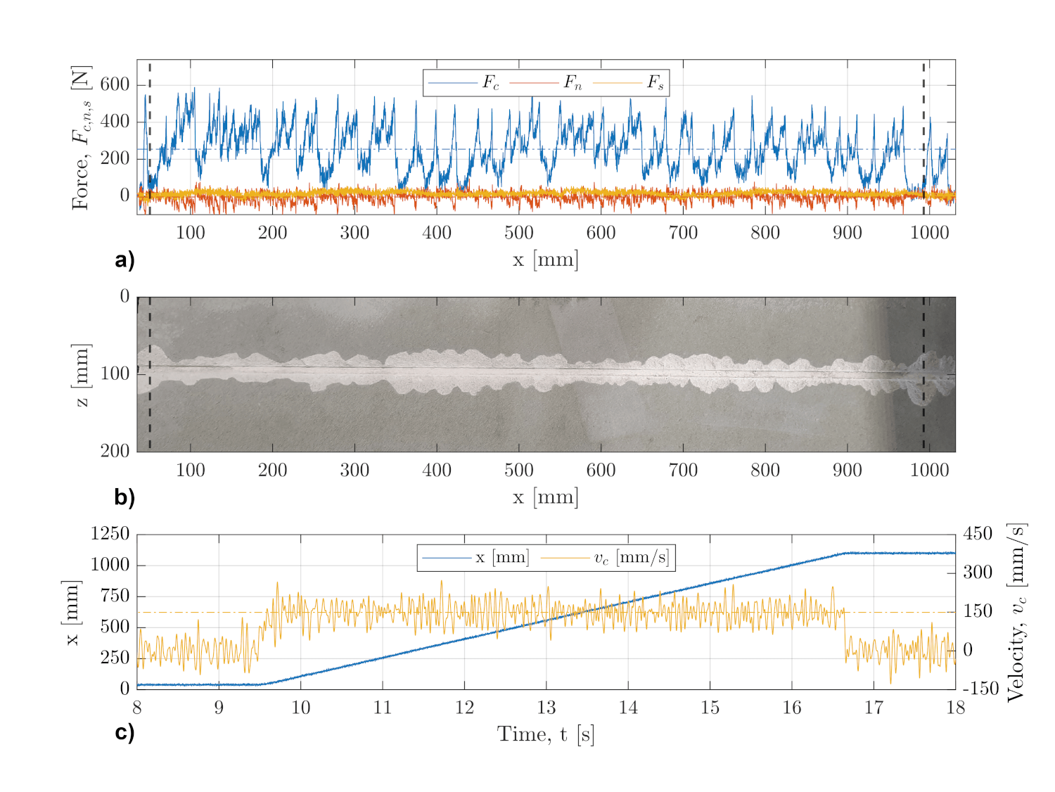
FIGURE 6

Linear rock cutting experiment nr. 3: raw data (A); cutting groove (B); and cutting distance measurement and resulting velocity (C).

Results

A typical result of a linear cutting experiment is shown in Figure 6. In Figure 6A, the cutting force (Fc), normal force (Fn) and side force (Fs) are plotted against the travelled distance through the rock sample in x-direction It can be clearly seen that after initial contact (x≈40mm) , the cutting force increases significantly and a typical sawtooth pattern is generated, indicating a brittle failure mechanism (Verhoef, 1997). This behaviour results from the generation of rock chips during the cutting process. The normal force is related to the cutting force but shows a negligible increase. More precisely, it is found that the average normal force is slightly negative. This is a result of the tool tip temporarily loosing contact with the bottom of the groove as a rock chip is released from the mass. At this instance, partially due to the rake angle of the chisel,the normal force can be directed downwards, causing it to be “pulled into” the rock mass. As chisel 1 was used during the experiment shown in Figure 6, this is to be expected. Finally, the side force measurement is shown to remain approximately zero over the total distance. Due to the linear motion of the chisel and constant depth of cut this measurement confirms that the chisel and rock sample are properly aligned with respect to the LRCS.

Furthermore, two vertical dashed lines are shown. These vertical lines indicate the cutoff distance from initial contact of the chisel with the rock as well as the cutoff distance from the chisel exiting the rock sample. Because a steady-state cutting process is required to determine the statistics during an experiment, these so-called "break-in" and "break-out" distances were calculated by defining a threshold force value that is an order of magnitude larger than the noise of the signal. The data points between these initial cutoff distances are used to compute the mean cutting force, after which the vertical lines are shifted one data point inwards, effectively shortening the steady-state section where a new mean cutting force is computed. This process is repeated until the difference between subsequent mean cutting force values equals 0.1 N. The statistics are then determined using the datapoints in the steady-state section of the measurement.

After the experiment, the resulting groove is cleaned by carefully removing the released rock chips (Figure 6B). The width of the groove is found to be significantly wider than the chisel width due to the side breakout angle s) (Roxborough, 1973). The collected rock chips and resulting groove can be used in a later stage to determine a particle size distribution (PSD) and specific energy. Finally, the displacement measurement is shown in Figure 6C. The experiment is characterised by a steady slope that leads to a constant cutting velocity of 0.15 m/s.

FIGURE 7

Repeatability LRCS

Setup performance

Three identical experiments (as shown in Table 2) were performed using Ytong limestone in order to address the repeatability of the setup. The results of these experiments are shown in Figure 7 using a box plot. Each of these experiments showed similar features as those described in Figure 6, where the cutting force was dominant, the normal force on average slightly negative due to the rake angle in combination with a sharp chisel geometry and the side force remained approximately zero.

Throughout the three experiments, it can be seen that the size of the boxes is very similar. The upper and lower length of the whiskers is found to be similar for the three experiments as well, indicating similar variability. Lastly, the overall mean of the cutting force was computed and determined to be Fc≈ 266 N. Another interesting finding is that the mean and median per experiment are approximately equal. This indicates a symmetrical distribution of the data, which physically means that the rock cutting process and thus behaviour is spatially consistent. To achieve this, the rock sample properties must be spatially consistent as well, indicating that this synthetic limestone might be considered homogeneous.

FIGURE 8

Effect of chisel wear (negative clearance angle) on the cutting and normal force.

Preliminary results on the effect of clearance angle

Finally, the effect of chisel wear is addressed by changing the clearance angle (γ) , while all other variables are kept constant (see Table 1 and 2). During the experiment a characteristic sound and vibrations were noticed, indicating that the cutting process was not as smooth as in the previous experiments. The resulting cutting and normal force as function of the cutting distance x are shown in Figure 8. Note that the length of the rock sample used for the worn chisel experiment (γ=-4°) is approximately 800 mm length, 200 mm shorter than the rock sample for the sharp chisel geometry (γ=5°)

Comparing the cutting forces for the sharp and worn chisel geometry it is found that the difference between local minima and maxima is larger for the worn chisel. This, however, is expected to be caused by the ductility number (m=UCS/BTS) that is slightly different for the two rock samples (Verhoef, 1997). Furthermore, it can be seen that both the cutting force as well as the normal force are increased due to the wear flat being in contact with the rock sample. Analysing the average cutting force to average normal force ratio for the sharp chisel yields Fc / Fn≈-55 due to the cutting force being dominant and the normal force being slightly negative. In this case, the angle of the total cutting force can be considered zero, i.e. in line with the cutting velocity. The addition of the wear flat being in contact with the rock sample results in this ratio yielding Fc / Fn≈1.23. This shows that the angle of the total cutting force is no longer zero but approximately 39°. This trend corresponds well with the findings of Dalziel and Davies (1964). Because the UCS is slightly larger for the Savonierres limestone (~22%), the increase of the normal force between the two experiments cannot be directly compared, but it does indicate that the presence of a wear flat area, including a negative clearance angle of only 4°, results in a significant increase.

Analysing the normal force for the negative clearance angle test, it is found that the fluctuation in force is less than the cutting force. While it is expected that the cutting force is mainly dominated by a brittle failure mechanism, the normal force resulting from the rock sample being compressed at the bottom of the chisel is dominated by a cataclastic ductile failure mechanism (Detournay and Defourny, 1992: Cools, 1993: Verhoef, 1997). The continuous crushing action underneath the wear flat could explain the apparently higher frequency in the normal force measurement.

FIGURE 9

The Young Author award was handed over by IADC’s Director Arnold de Bruijn (right) to Rick van de Wetering for his contribution to the paper “A laboratory scale linear rock cutting setup to study cutting forces of blunt chisels”. The Young Author Award is granted at industry-leading conferences with 2025’s winning young author selected from the proceedings of the 24th WODCON Congress, held from 23-27 June 2025 in San Diego, USA.

Conclusion

In this article, the LRCS that was designed and build at the Royal IHC laboratory is presented. This setup allows for a parametric study of the chisel geometry and rock sample properties. Using two, decoupled 6-DOF sensors, cutting and normal forces can be measured up to 20 kN, using chisel of 10 and 20 mm wide and a velocity range of 0.01-0.22 m/s. The maximum rock sample geometry allowed is 1100 x 300 x 300 mm.

Conducting three comparable experiments using a sharp chisel geometry in Ytong rock samples (synthetic limestone), resulted in the average normal force being slightly negative and the average side force remaining approximately zero. The cutting force was concluded to be similar throughout the three experiments with respect to the mean, median and the variability. From these findings it was concluded that the setup performs as expected.

Altering the chisel geometry by introducing a wear flat area in combination with a negative clearance angle resulted in a significant increase in the normal force while the cutting force was less affected. This finding was in good agreement with results found in literature and led to the conclusion that the measuring section is properly designed.

Summary

This article explains the linear rock cutting setup designed and built at the Royal IHC laboratory to study the effect of a worn or blunt chisel geometry on the cutting forces, with the emphasis on the normal force. To test the repeatability and accuracy of the setup, three comparable experiments were conducted using a sharp chisel. From the resulting cutting forces it was concluded that the setup performed as expected as the recorded cutting force was within 16% throughout the three experiments using synthetic limestone. Furthermore, the normal force was found to be slightly negative, effectively pulling the chisel into the rock. This corresponds with findings in literature. Finally, an experiment was conducted where a worn chisel geometry was used, resulting in an increased cutting force, but a significantly stronger increase in the normal force. This implies that the normal force is strongly dependent on wear and cannot be omitted when cutting rock with a chisel.

Authors

Rick van de Wetering

Rick is a research and development engineer at Royal IHC and a part-time PhD candidate of Offshore and Dredging Engineering at the department of Maritime and Transport Technology, Delft University of Technology, in the Netherlands. He specialises in excavation technology for the dredging and wet mining industry. Rick’s research focuses on the physics involved while mechanically excavating soil or rock, combining experimental and analytical techniques into applicable models.

OTHER ARTICLES BY THIS AUTHOR
Dr. Miguel Angel Cabrera

Miguel is an assistant professor of experimental soil mechanics at the Geo-Engineering department of Delft University of Technology where he works on the physical modelling of land instabilities and soil-structure interaction systems. His research in geomechanics focuses on complex, multiphase, geophysical and environmental flows, and interaction systems between soil and fluid. To this end, Miguel develops and uses a combined approach of physical modelling, advanced measurement techniques and numerical modelling.

OTHER ARTICLES BY THIS AUTHOR
Dr. Mario Alvarez Grima

Mario is principal research and development specialist at Royal IHC with over 30 years of experience in geo-engineering. He specialises in process modelling for dredging and wet mining, combining analytical, numerical and AI methods with lab and field data. He holds a PhD from Delft University of Technology on AI applications in geo-engineering and has led multidisciplinary projects on rock cutting and dynamic soil structure interaction. Mario has published extensively in international journals and conferences.

OTHER ARTICLES BY THIS AUTHOR
Frits Hofstra

Frits is a senior specialist at Royal IHC on the interface between dredging technology and mechanical engineering. He has worked on slurry transport in pumps and drag heads, focusing on material transport and the resulting loads on the systems. Currently Frits’ research focuses on mechanical excavation of soil and rock for the dredging and wet mining industries and methods for the improvement thereof.

OTHER ARTICLES BY THIS AUTHOR
Dr. ir. Rudy Helmons

Rudy is an associate professor in Offshore and Dredging Engineering at the Department of Maritime and Transport Technology, Delft University of Technology. His research focuses on physical processes related to dredging and seabed mining, including mechanical and hydraulic excavation, hydraulic transport and sediment dynamics. He has been involved in several deep-sea mining projects and has a solid background in mechanical engineering and fluid mechanics. Rudy served as the second supervisor for the thesis work from Delft University of Technology.

OTHER ARTICLES BY THIS AUTHOR

PDF download

Download the PDF version of this article with high resolution pictures and layout.

Single-page view

DOWNLOAD PDF Document | 2,98 MB

Two-page view

DOWNLOAD PDF Document | 2,96 MB

Share this page